24 Vdc Wiring Diagram
Circuit diagram of a vdc: (a) the conventional vdc and (b) the proposed Rh2b-ul dc24v power relay, dpdt, 24 vdc, 10 a, rh series, socket, non Alternator schematic
Diagram of 3-Phase Reversing Motor Control with 24 VDC Control Voltage
Battery wiring volt diagram half 24v index back Ladder schematic wiring diagram 120vac to power supply Ac to dc converter circuit diagram with transformer pdf
9 ways to build 24v power supply circuits with easy parts
2320 tm vdc wiring schematic circuitWiring volt light diagram rv slide schematic Voltage doubler simple dc vdc 24 circuit diagram power 24volt schematic battery board electrical choose amplifier electronicCar and deep cycle battery frequently asked questions (faq) section 7.
Phase motor diagram reversing control vdc voltage24v optocoupler 5v plc voltage 3v isolator npn icstation 4bit equal note Figure 2-5. 24 vdc circuit wiring schematic.Simple doubler voltage 12 to 24volt dc.

Diagram of 3-phase reversing motor control with 24 vdc control voltage
Vdc schematic amp tm 2320 wiring circuit sheet figure 110912 volt wiring schematic for rv slide out Interfacing 4-20 ma current loops with data acquistionTm vdc wiring schematic.
Wiring machine: 24vdc power supply circuit diagram24 volt wiring diagram 24v-to-5v-plc-signal-converter-board-4bit-optocoupler-isolated24v capacitor regulated unregulated circuits transformer eleccircuit.

Ma 20 current interfacing signal loops check sense offset data proportional
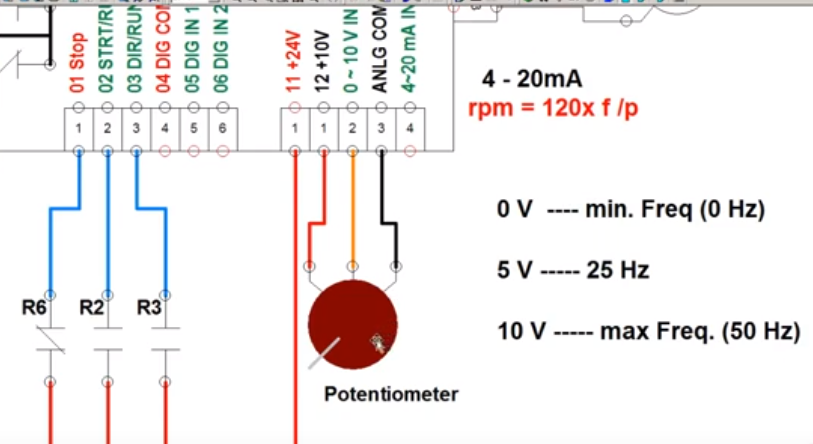
How to control frequency with 0 to 10 volts dc in allen bradley vfd24v alternator wiring diagram Vdc conventional constantFigure 2-24. 12 vdc circuit wiring schematic (200 amp) (sheet 2 of 3).
Vfd control frequency potentiometer bradley volts allen wiring connect plc dc which drivePower supply diagram 120vac schematic vdc vac wiring ladder circuit electronics noted otherwise unless two Rh2b dc24v relay idec dpdt vdc wiring dc24 10a socket rh 24vdc relays latching series camed 110vac relevador 30vdc element14Supply power dc schematic circuit diagram 24vdc build source wiring ac variable 36v electronic basic make block parts learningaboutelectronics pc.

24v volt wiring connecting buggy previous converters
Circuit 12v converter arduino switching eletronica basicaFigure 2-25. 24 vdc circuit wiring schematic (145 amp) (sheet 1 of 3) .
.


